picoaudio
A Bluetooth A2DP audio receiver for the Raspberry Pi Pico 2 W. It receives Bluetooth audio and outputs 16-bit stereo PCM over I2S to a CJMCU-1334 (UDA1334A) DAC.
Built using the BTstack library and the Pico C/C++ SDK.
Architecture & Features
- Dual-Core Architecture: Offloads the heavy SBC audio decoding entirely to Core 1 via a hardware-spinlock queue, ensuring that the Bluetooth stack on Core 0 never drops packets due to CPU starvation.
- Ultra-Low Latency: Optimized buffer sizes (I2S DMA and thread-safe queue) to achieve ~55ms total audio latency, perfect for lip-synced video playback.
- Multipoint Bluetooth (Dual Device): Supports 2 simultaneous A2DP and AVRCP connections. The firmware intelligently multiplexes incoming streams by maintaining independent connection states, decoding only the active stream, and dynamically switching to the standby device when the primary stream pauses. Volume is handled completely independently for each device.
- A2DP Sink & SBC Decoder: Receives SBC encoded audio (up to Bitpool 53 / ~328 kbps) and decodes it to 16-bit PCM stereo.
- Hardware I2S Output: Uses PIO and DMA to stream decoded audio to the I2S DAC at 44.1 kHz.
- Drift Synchronization: Implements dynamic software resampling (
btstack_resample) to synchronize the incoming Bluetooth clock with the RP2350 hardware I2S clock, preventing buffer under/overflows. - Hardware Mute & AVRCP Volume: Physical GPIO toggles hardware mute on the DAC. Processes AVRCP absolute volume commands and applies a logarithmic (quadratic) scaling function to the PCM data in software.
- UI Sound Synthesizer: Contains a blocking square-wave synthesizer that injects status tones directly into the I2S hardware pool on boot, connection, and disconnection events.
Data Flow
  ┌──────────┐     Bluetooth      ┌─────────────────────────────────────┐
  │          │   A2DP / SBC       │        Raspberry Pi Pico 2 W        │
  │  Phone   │ ─── ~328 kbps ──> │                                     │
  │          │   (wireless)       │  CYW43439 Radio                     │
  └──────────┘                    │       │                             │
                                  │       v                             │
                                  │ [CORE 0] BTstack (A2DP Sink)        │
                                  │       │                             │
                                  │       v (Thread-Safe Queue)         │
                                  │ [CORE 1] SBC Decoder (bitpool 53)   │
                                  │       │                             │
                                  │       v                             │
                                  │ [CORE 1] Volume Scaling (AVRCP)     │
                                  │       │                             │
                                  │       v                             │
                                  │ [CORE 1] DMA -> PIO I2S State Mach. │
                                  │       │                             │
                                  └───────┼─────────────────────────────┘
                                          │
                              GPIO 16 (BCLK)
                              GPIO 17 (WSEL)    I2S Bus (3 wires)
                              GPIO 18 (DIN)
                                          │
                                          v
                                  ┌───────────────┐
                                  │  CJMCU-1334   │
                                  │  (UDA1334A)   │
                                  │               │
                                  │  I2S -> DAC   │
                                  │       │       │
                                  │   3.5mm Jack  │
                                  └───────┼───────┘
                                          │
                                          v
                                    Speaker / Headphones
UI Sound Configuration
The status tones are generated mathematically via bt_audio.c. Configuration is managed via preprocessor macros:
ENABLE_UI_SOUNDS(default:1): Set to0to disable the synthesizer.UI_SOUND_VOLUME(default:50): Sets the 16-bit PCM amplitude of the square wave (max 32767).
Hardware Requirements
| Component | Role |
|---|---|
| Raspberry Pi Pico 2 W | Main controller (RP2350 + CYW43439) |
| CJMCU-1334 (UDA1334A) | I2S DAC |
Wiring Guide
Connection Diagram
                    ┌──────────────────┐
              ┌─────┤ USB              ├─────┐
              │     └──────────────────┘     │
   UART0 TX ──┤ GP0  (1)        (40) VBUS   ├── 5V USB Power ──────> CJMCU VIN
   UART0 RX ──┤ GP1  (2)        (39) VSYS   │
              ┤ GND  (3)        (38) GND    ├── Ground ─────────────> CJMCU GND
 Play/Pause ──┤ GP2  (4)        (37) 3V3_EN  │
       Mute ──┤ GP3  (5)        (36) 3V3 OUT │
  Volume Up ──┤ GP4  (6)        (35) ADC_REF │
Volume Down ──┤ GP5  (7)        (34) GP28/A2 │
              ┤ GND  (8)        (33) GND     │
  Next Song ──┤ GP6  (9)        (32) GP27/A1 │
  Prev Song ──┤ GP7  (10)       (31) GP26/A0 │
    Pairing ──┤ GP8  (11)       (30) RUN     │
              ┤ GP9  (12)       (29) GP22    │
              ┤ GND  (13)       (28) GND     │
              ┤ GP10 (14)       (27) GP21    │
              ┤ GP11 (15)       (26) GP20    │
              ┤ GP12 (16)       (25) GP19    │
              ┤ GP13 (17)       (24) GP18    ├── I2S Data (DIN) ────> CJMCU DIN
              ┤ GND  (18)       (23) GND     │
              ┤ GP14 (19)       (22) GP17    ├── I2S WSEL ──────────> CJMCU WSEL
   DAC Mute ──┤ GP15 (20)       (21) GP16    ├── I2S BCLK ──────────> CJMCU BCLK
              └──────────────────────────────┘
                     Raspberry Pi Pico 2 W
Pin Table
| Pico 2 W Pin | Physical Pin | CJMCU-1334 | Signal |
|---|---|---|---|
| VBUS | 40 | VIN | 5V USB Power |
| GND | 38 | GND | Common Ground |
| GPIO 16 | 21 | BCLK | I2S Bit Clock |
| GPIO 17 | 22 | WSEL | I2S Word Select (L/R) |
| GPIO 18 | 24 | DIN | I2S Serial Data |
[!NOTE] VBUS (5V) is used instead of 3V3. The Pico’s switching 3V3 regulator introduces noise; feeding 5V to the DAC’s onboard LDO provides cleaner power for the analog output.
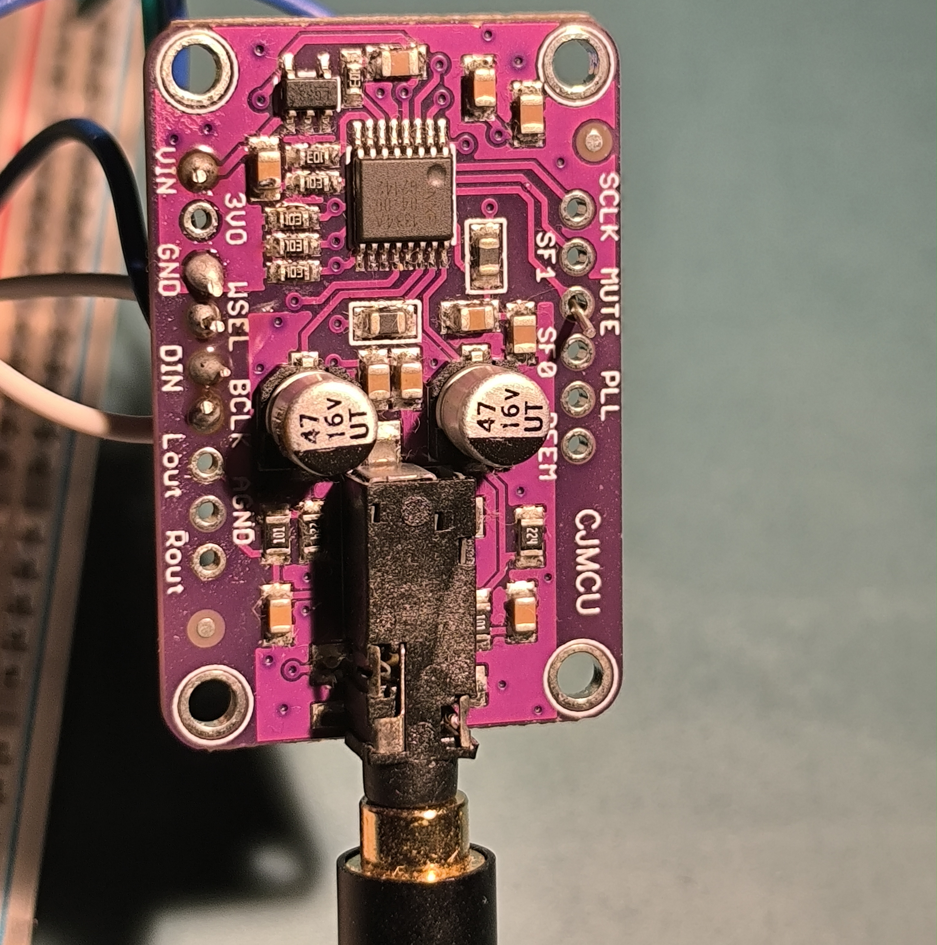
DAC Configuration Pins (CJMCU-1334)
Most breakout boards pull these low by default:
- SF0 / SF1: LOW (I2S format)
- PLL: LOW (Audio PLL mode)
- DEEM: LOW (De-emphasis OFF)
- MUTE: LOW (Mute OFF)
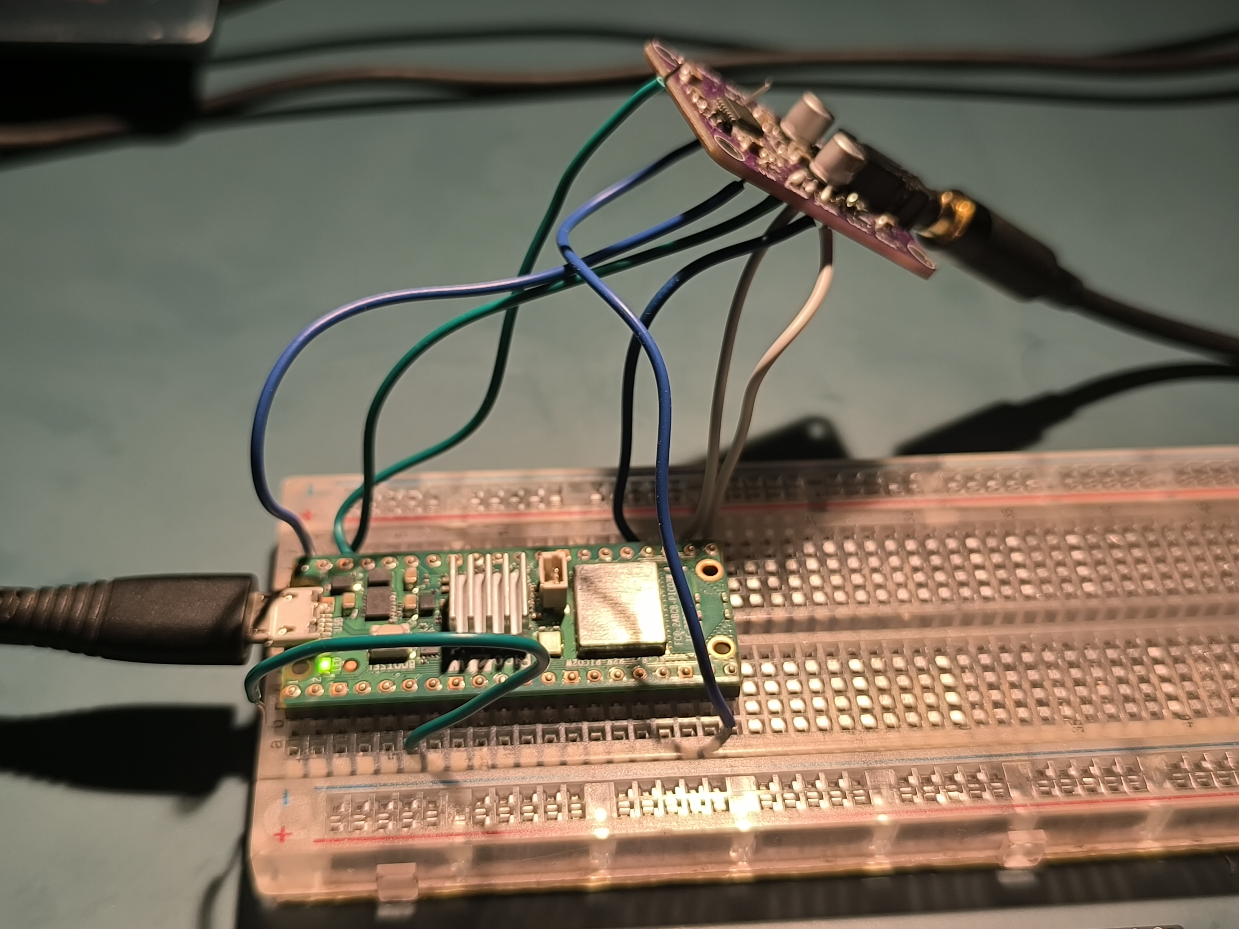
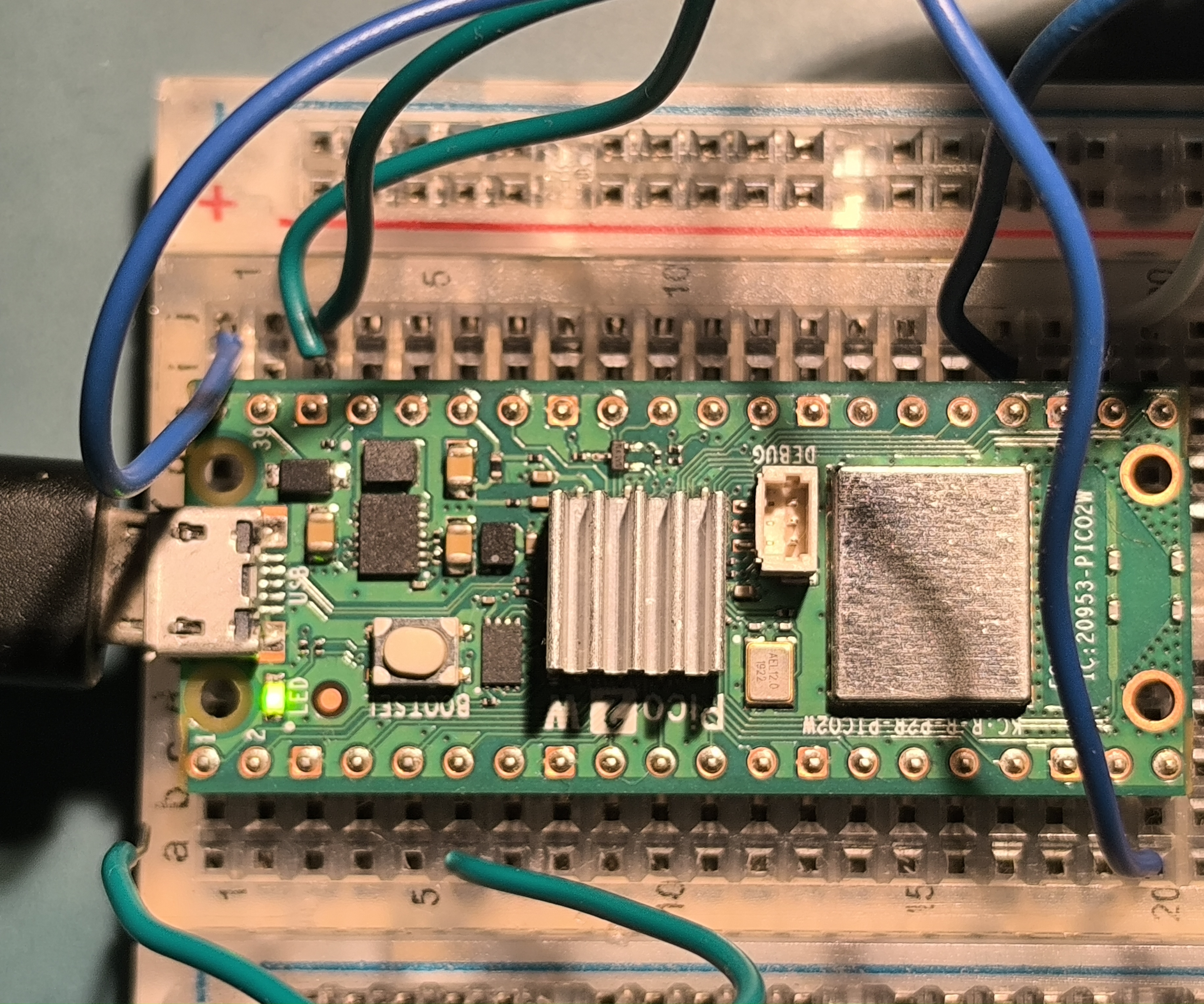
Hardware Setup & Demo
Project in Action
Here is the receiver in action! The Raspberry Pi Pico 2 W and the CJMCU-1334 DAC board are connected directly to a 2.1 channel sound system through the 3.5mm audio jack.
Wiring Closeups
Serial Logs
Download Latest Firmware
You can download the pre-compiled .uf2 firmware from the latest successful build here:
Download Latest Firmware (pico-audio-firmware.zip)
(Extract the .zip to find the .uf2 file, then follow the flashing instructions below).
Build Instructions
- Install and configure the Raspberry Pi Pico C/C++ SDK for the RP2350.
- Clone the repository.
- Build the project:
mkdir -p build && cd build
cmake -DPICO_BOARD=pico2_w ..
ninja
Flashing
- Hold the BOOTSEL button on the Pico 2 W while plugging in the USB cable.
- A mass storage device named
RP2350will mount. - Copy the compiled
.uf2binary to the device:
cp build/bluetooth_audio_receiver.uf2 /run/media/$USER/RP2350/- The Pico will automatically reboot. The Bluetooth device name is Pico2W-Audio.
LED Status Indicator
| LED State | Meaning |
|---|---|
| 1 Hz Blink | Discoverable / Waiting for pairing |
| 4 Hz Blink | Connected, no active audio stream |
| Solid ON | Connected, audio streaming |
| OFF | Initialization error |
Troubleshooting
| Symptom | Cause | Resolution |
|---|---|---|
| No LED blink on boot | CYW43 init failure | Verify USB power, reflash .uf2 |
| Volume buttons unresponsive | AVRCP sync failure | Re-pair the device; check UART logs for [avrcp] |
| Audio distortion | Floating DAC config pins | Bridge SF0 and SF1 to GND on the DAC board |
References
License
Licensed under the MIT License. See LICENSE for details.